The maintenance sequence below begins with evidence from operation and then moves toward an isolated internal inspection.
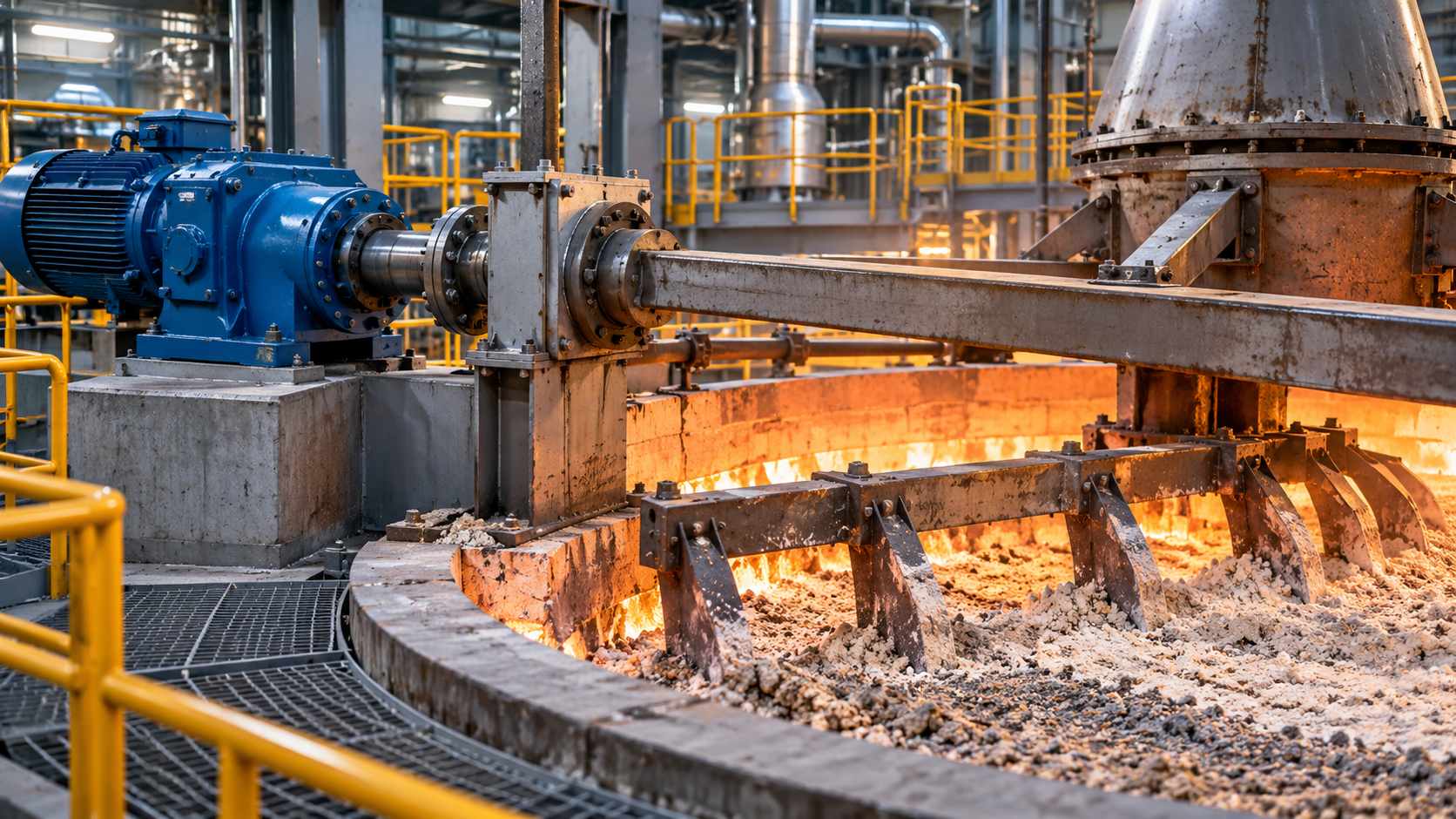
Maintain a Mannheim furnace rake arm by inspecting the drive, shaft, bearings, seals, rake teeth, clearances, and furnace-bottom deposits at defined operating intervals. Trend torque, speed, vibration, and discharge behavior together. A small change in load or sound can reveal misalignment, buildup, worn teeth, or a sealing problem before the arm becomes difficult to turn.
Why the Rake Arm Deserves a Dedicated Plan
The rake arm is both a mixing device and a material-transfer device. In a Mannheim SOP plant, it helps keep potassium chloride and sulfuric acid in contact while moving reacted potassium sulfate toward discharge. Its working environment combines heat, acidic vapors, abrasive solids, thermal expansion, and restricted access.
Routine maintenance therefore has two parts. The first is mechanical: drive, shaft, bearings, couplings, seals, and supports. The second is process-facing: rake-to-floor clearance, tooth condition, material buildup, residence time, and discharge behavior. A mechanically healthy drive can still produce poor results if the rake geometry is worn or the furnace bottom is obstructed.
Maintenance Prerequisites
Before an inspection, confirm the isolation and cooling conditions specified by the site procedure. Prepare:
- Approved lockout, isolation, cooling, atmosphere-testing, and entry permits.
- Recent torque, speed, vibration, bearing-temperature, and motor-current trends.
- Furnace drawings showing shaft, rake arms, teeth, seals, access points, and clearances.
- Replacement teeth, fasteners, seals, lubrication, and a method for recording wear.
- A clean handover between operations, maintenance, refractory specialists, and the HCl recovery team.
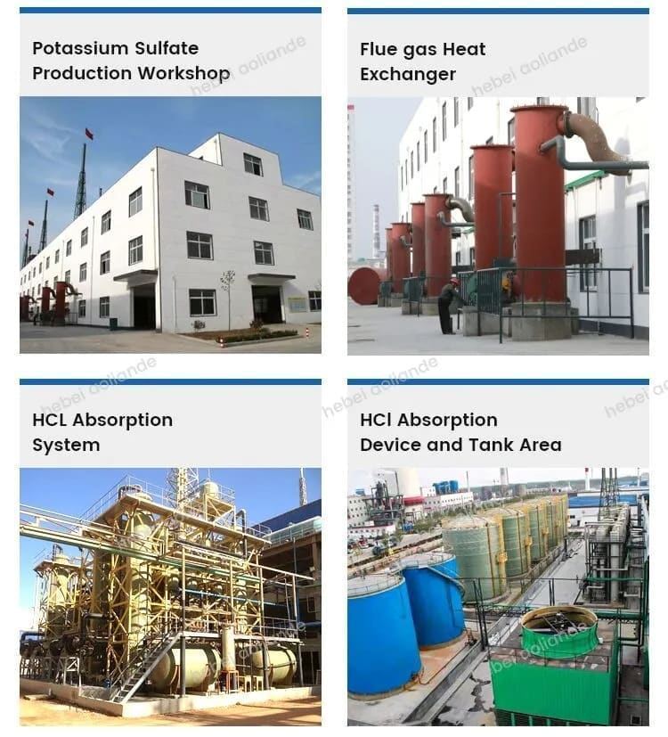
The Mannheim process equipment layout should be included with the permit pack so the team can identify drive access, inspection openings, seals, discharge points, and nearby acid-gas systems before entering the work area.
Never infer that a furnace is safe to enter from surface temperature alone. The permit and gas-test process controls entry; the maintenance checklist controls what is examined once access is authorized.
Step-by-Step Inspection Method
The inspection moves from operating evidence to external components and then to the furnace interior. Keeping that order reduces unnecessary entry work and gives the maintenance team a baseline for every finding.
Step 1: Review operating history before opening the furnace
Look for gradual torque rise, speed fluctuations, motor-current spikes, unusual vibration, repeated overload trips, or changes in discharge rate. Match these trends with feed moisture, KCl condition, sulfuric acid flow, furnace temperature, and recent cleaning.
A slow torque increase points toward buildup, clearance loss, or increasing friction. A sudden spike deserves a different response: foreign material, a broken tooth, shaft movement, or a drive fault may be involved. The trend is often more useful than a single alarm value.
Step 2: Inspect the external drive train
Check the motor, gearbox, coupling, baseplate, guards, shaft seal area, and accessible bearings. Look for oil leakage, dust packed around a seal, loose foundation bolts, coupling element damage, and evidence of thermal movement.
Compare actual speed with the control-system command. If speed is correct but torque is rising, the problem may be inside the furnace. If speed hunts or fails to reach command, inspect the drive, gearbox, coupling, and control loop before disturbing the rake.
Step 3: Check shaft alignment and support condition
Thermal expansion can change alignment between cold inspection and hot operation. Examine shaft runout where accessible, bearing support condition, coupling alignment records, and any contact marks around the seal or guide.
Do not correct alignment by moving one support without checking the full shaft line. A small geometric change at the drive can alter rake clearance at the furnace bottom and increase wear during the next campaign.
Step 4: Inspect rake arms and teeth
Measure tooth wear, arm straightness, fastener condition, and the shape of the working edge. Look for rounded teeth, cracks, missing retainers, bent arms, and deposits that change the intended material path. Photograph each zone and mark the position on the maintenance drawing.
Rake geometry affects both mixing and residence time. A missing or shortened tooth can leave a stagnant pocket, while a bent arm may scrape the furnace bottom and produce a sudden torque increase. Replacement parts should match the approved material, profile, and fastening method.
Step 5: Verify clearances and furnace-bottom condition
Measure the rake-to-floor clearance at the approved inspection points. Check for refractory heave, local deposits, cracks, loose lining, or a discharge opening partly blocked by sintered material. A clearance that is acceptable at one location can be tight at another after thermal cycling.
The inspection should distinguish removable process buildup from refractory damage. Mechanical force applied to a damaged lining can turn a cleaning job into a major repair.
Step 6: Inspect seals and prevent vapor ingress
Inspect shaft seals, packing, gland hardware, cooling or purge connections, and nearby corrosion. A seal problem can allow acidic vapor into the drive area, contaminate lubricant, and accelerate bearing or coupling damage.
If a purge is used, verify flow, pressure, filtration, and alarm response. Replacing packing without correcting a blocked purge or misaligned shaft usually produces a short-lived repair.
Step 7: Test under controlled load after maintenance
After reassembly, confirm fastener torque, guard installation, lubrication, interlocks, rotation direction, and emergency-stop operation. Start at the approved low-load condition and listen for rubbing, rhythmic knocks, or speed hunting.
Compare torque, vibration, bearing temperature, and discharge behavior with the pre-maintenance baseline. Increase feed gradually; do not declare success only because the motor turns without tripping.
Inspection Frequency and Evidence
| Item | What to trend or inspect | Escalation signal | Maintenance evidence |
| Drive torque | Average and peak load | Progressive rise or spikes | Trend with feed and temperature |
| Gearbox and bearings | Temperature, oil, vibration | Heat, noise, metal particles | Lubricant and vibration record |
| Shaft and seals | Runout, leakage, purge | Contact marks or vapor ingress | Alignment and seal report |
| Rake arms | Straightness, fasteners, wear | Bent arm or loose tooth | Photos and measured wear |
| Furnace bottom | Clearance and deposits | Scraping, heave, blocked outlet | Clearance map and cleaning log |
| Product discharge | Rate and accumulation | Back-up or residence-time shift | Operating handover note |
Set frequencies using duty cycle, material behavior, manufacturer guidance, and the consequences of failure. A visual check can be frequent; a full internal inspection belongs in a planned outage with the right permits and spare parts.
Common Failure Patterns
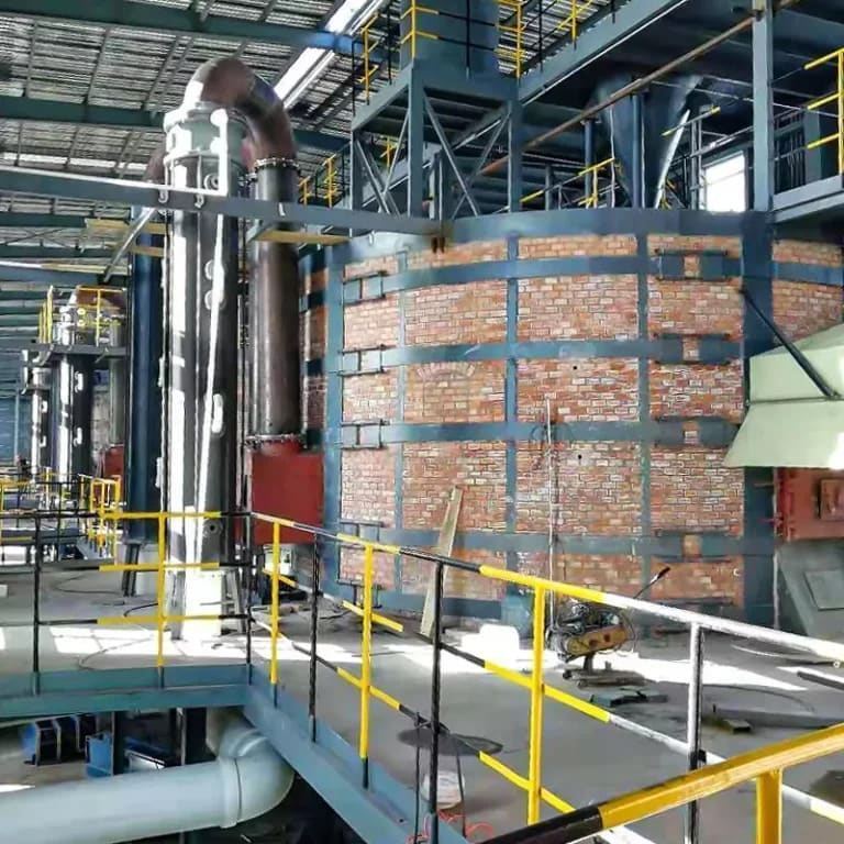
The patterns below are starting points for diagnosis. Verify the mechanical condition, process history, and instrument signal together before deciding whether the next action is adjustment, cleaning, repair, or an outage.
Rising torque with normal speed
Check furnace-bottom deposits, clearance loss, tooth wear, and material moisture. Review whether the increase followed a feed or temperature change. Do not keep raising motor capacity to hide a mechanical restriction.
Vibration at one speed band
Inspect balance, shaft runout, coupling alignment, bearing condition, and a possible bent rake arm. A resonance-like signal can appear only at a particular speed, so test across the approved range and record the exact condition.
Seal leakage and dirty lubricant
Examine purge flow, packing compression, shaft finish, alignment, and vapor temperature. The source may be upstream of the seal rather than the seal material itself.
Uneven discharge or unreacted material
Review rake-to-floor clearance, tooth arrangement, feed distribution, furnace temperature profile, and discharge opening condition. Mechanical maintenance and process adjustment may be needed together.
For project planning, the Mannheim SOP production line specification should identify the rake drive arrangement, access points, sealing concept, inspection tools, spare-parts package, and commissioning tests.
The potassium sulfate production equipment should be reviewed with the maintenance philosophy. Confirm which wear parts are intended for routine replacement, which inspections require an outage, and how drive data will be trended in the control system.
The Mannheim furnace engineering support should document the commissioning baseline and the maintenance boundary so future outage teams know which measurements are comparable from one campaign to the next.
Supplier Scope
Hebei Aoliande Chemical Equipment Co., LTD. supplies Mannheim process potassium/sodium sulfate production line equipment, including furnace-related systems, material handling, HCl recovery interfaces, controls, and project support. Buyers should provide KCl and sulfuric acid conditions, target product, utilities, operating schedule, local codes, and maintenance access requirements so the rake and drive system are designed for the actual duty.
The maintenance package should be agreed before fabrication. It should identify inspection openings, lifting points, special tools, recommended spare teeth and seals, lubrication grades, alignment references, and the information recorded during commissioning. A useful drawing set marks the rake positions and gives a measurement method that can be repeated at every outage.
Commissioning records should include unloaded rotation, low-load rotation, interlock checks, vibration readings, bearing temperatures, torque response, and the first stable discharge observation. Those records are more valuable than a generic statement that the drive passed a factory test because they create a baseline for the actual furnace installation.
Conclusion
Rake-arm reliability is a combined mechanical and process issue. Trending torque and vibration, inspecting teeth and clearances, protecting seals, and testing under controlled load gives maintenance teams evidence before a small defect becomes a furnace outage. The best maintenance plan also records what changed, where it changed, and how the product and drive responded afterward.
FAQs
The following answers summarize the inspection decisions that are most useful during planned maintenance.
What is the first sign of rake-arm trouble?
A gradual torque increase, a new rhythmic vibration, speed fluctuation, or a change in discharge behavior can be an early sign. Compare the signal with feed, temperature, and recent cleaning history before choosing an intervention.
How often should rake teeth be replaced?
Replacement depends on wear rate, material abrasiveness, furnace duty, and the allowable profile change. Measure teeth during planned inspections and replace them when the approved geometry or clearance is no longer maintained.
Can a seal be replaced without checking alignment?
It can be physically replaced, but a misaligned shaft or blocked purge can quickly damage the new seal. Alignment, shaft condition, and purge performance should be checked as part of the repair.
Why does furnace-bottom clearance matter?
Clearance controls mixing, material movement, and mechanical load. Too little clearance can cause scraping and torque spikes; too much or uneven clearance can leave stagnant material and reduce movement toward discharge.